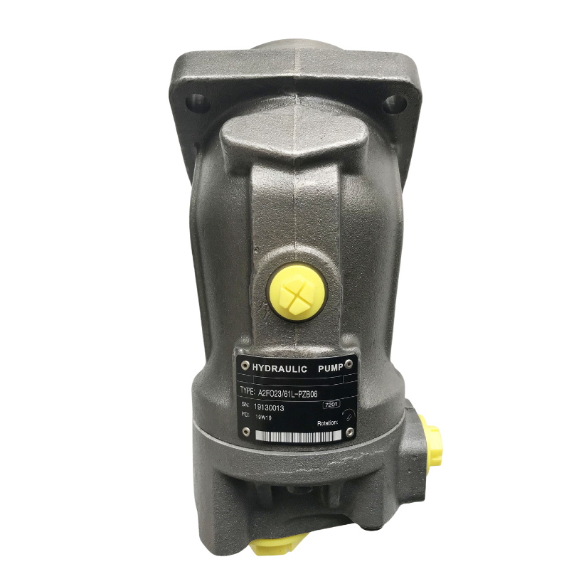
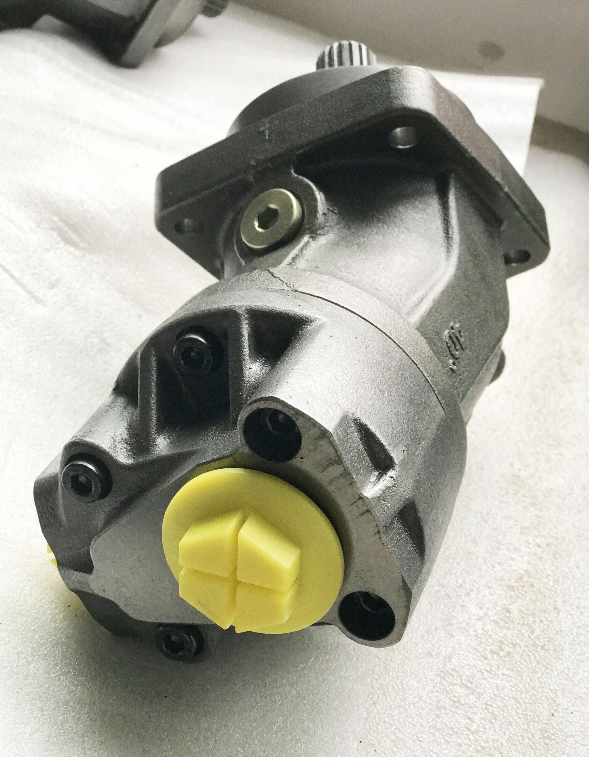
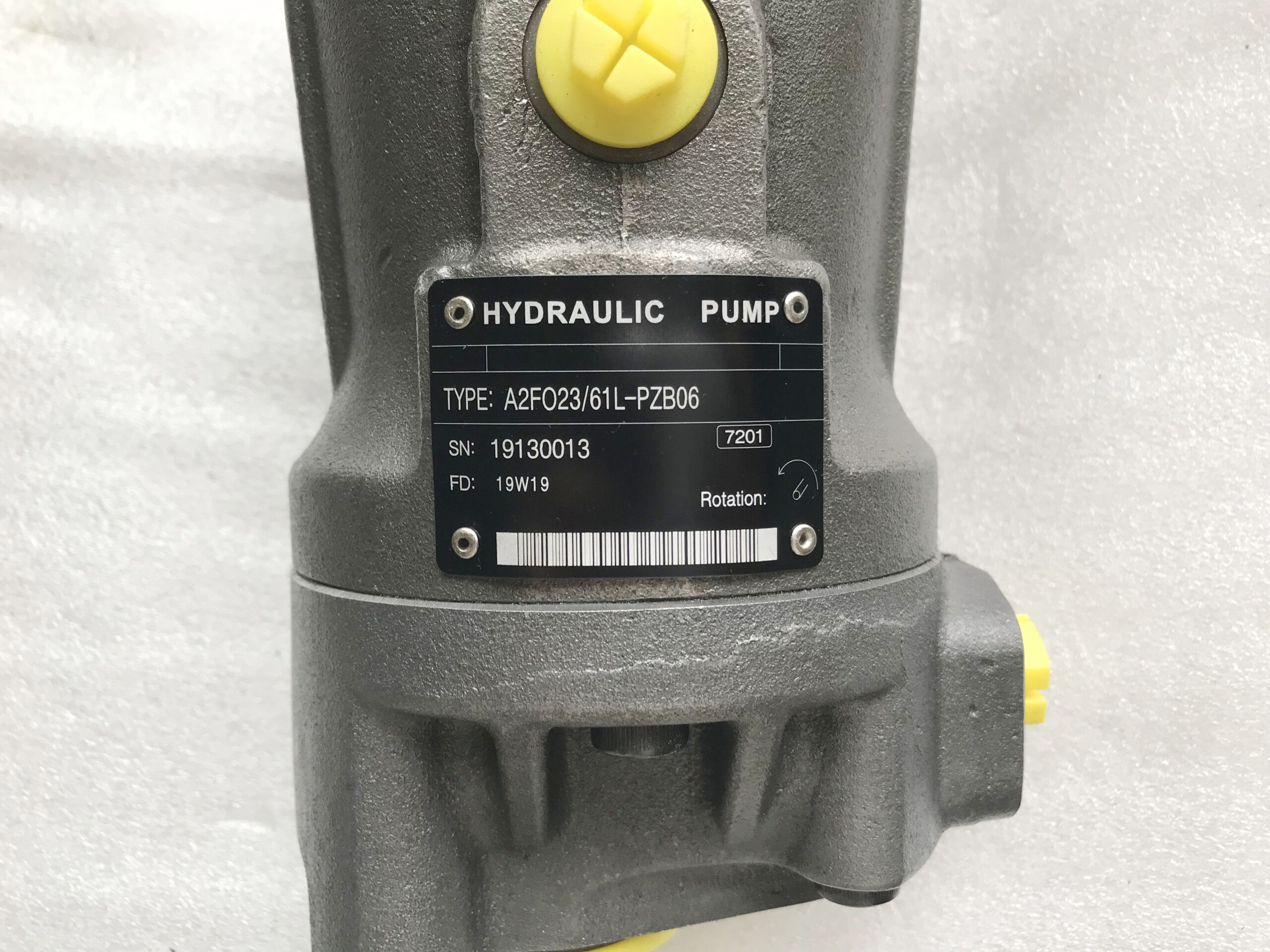
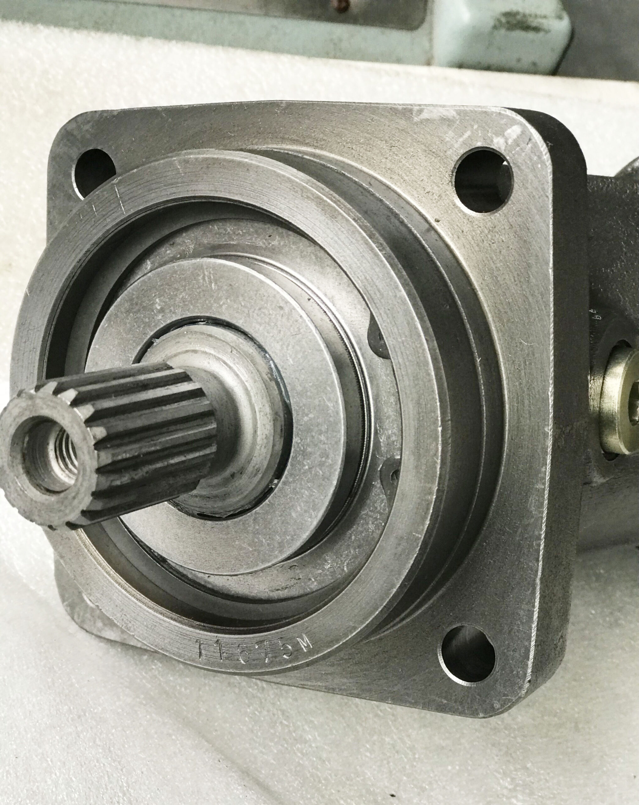
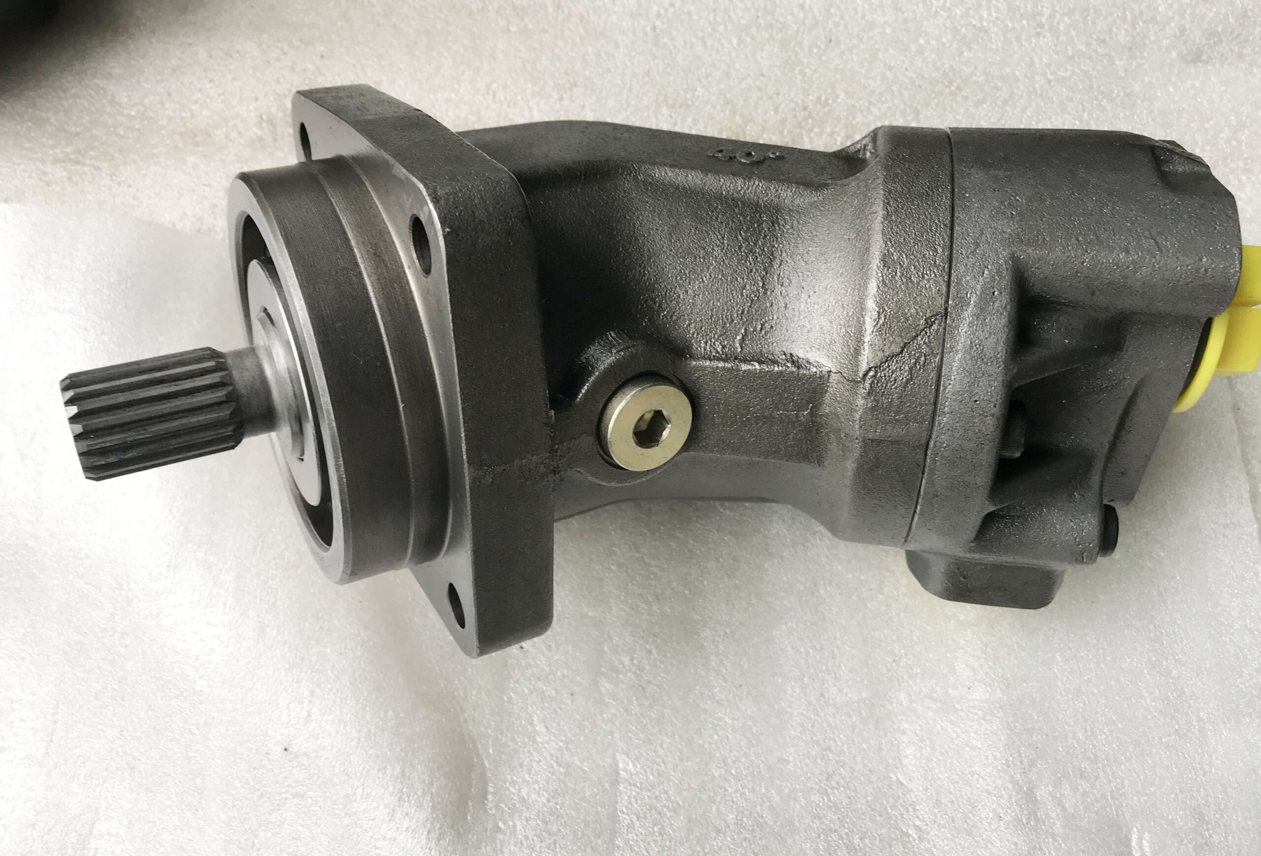
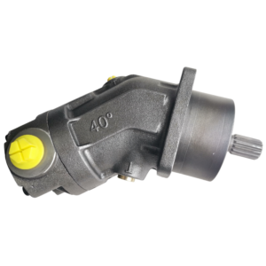
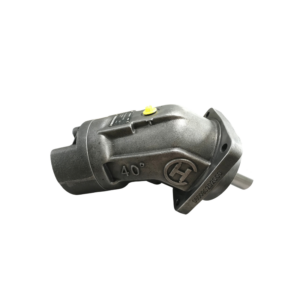
Rexroth A2FO32/61L-PZB06 Hydraulic Pump
The Rexroth A2FO32/61L-PZB06 Hydraulic Pump offers a wide range of benefits: easy installation, low noise and vibration levels, long service life and high efficiency at all temperatures. The A2FO32/61L-PZB06 hydraulic pump has become the benchmark for modern small hydraulic drives in the market.
Features
- Robust pump with long service life
- Very high total efficiency
- High power density
- Large variety of available nominal sizes allows exact adjustment to the application
- Optional with long-life bearings for the nominal sizes 250 to 1000
- Bent-axis design
Technical data
| Size | 5 | 10 | 12 | 16 | 23 | 28 | 32 | 45 | 56 | 63 | 80 | 90 | 107 | 125 | 160 | 180 | 200 | 250 | 355 | 500 | 710 | 1000 | |||
| Displacement geometric, per revolution |
Vg | cm³ | 4.93 | 10.3 | 12 | 16 | 22.9 | 28.1 | 32 | 45.6 | 56.1 | 63 | 80.4 | 90 | 106.7 | 125 | 160.4 | 180 | 200 | 250 | 355 | 500 | 710 | 1000 | |
| Nominal pressure | pnom | bar | 315 | 400 | 400 | 400 | 400 | 400 | 400 | 400 | 400 | 400 | 400 | 400 | 400 | 400 | 400 | 400 | 400 | 350 | 350 | 350 | 350 | 350 | |
| Maximum pressure | pmax | bar | 350 | 450 | 450 | 450 | 450 | 450 | 450 | 450 | 450 | 450 | 450 | 450 | 450 | 450 | 450 | 450 | 450 | 400 | 400 | 400 | 400 | 400 | |
| Maximum speed | nnom 1) | rpm | 5600 | 3150 | 3150 | 3150 | 2500 | 2500 | 2500 | 2240 | 2000 | 2000 | 1800 | 1800 | 1600 | 1600 | 1450 | 1450 | 1550 | 1500 | 1320 | 1200 | 1200 | 950 | |
| nmax 2) | rpm | 8000 | 6000 | 6000 | 6000 | 4750 | 4750 | 4750 | 4250 | 3750 | 3750 | 3350 | 3350 | 3000 | 3000 | 2650 | 2650 | 2750 | 1800 | 1600 | 1500 | 1500 | 1200 | ||
| Flow | at nnom | qV | l/min | 27.6 | 32 | 38 | 50 | 57 | 70 | 80 | 102 | 112 | 126 | 145 | 162 | 171 | 200 | 233 | 261 | 310 | 375 | 469 | 600 | 852 | 950 |
| Power | at nnom and pnom | P | kW | 14.5 | 22 | 25 | 34 | 38 | 47 | 53 | 68 | 75 | 84 | 96 | 108 | 114 | 133 | 155 | 174 | 207 | 219 | 273 | 350 | 497 | 554 |
| Torque 3) | at pnom | M | Nm | 24.7 | 66 | 76 | 102 | 146 | 179 | 204 | 290 | 357 | 401 | 512 | 573 | 679 | 796 | 1021 | 1146 | 1273 | 1393 | 1978 | 2785 | 3955 | 5570 |
| Rotary stiffness | c | kNm/rad | 0.63 | 0.92 | 1.25 | 1.59 | 2.56 | 2.93 | 3.12 | 4.18 | 5.94 | 6.25 | 8.73 | 9.14 | 11.2 | 11.9 | 17.4 | 18.2 | 57.3 | 73.1 | 96.1 | 144 | 270 | 324 | |
| Moment of inertia for rotary group | JTW | kg·m² | 0.00006 | 0.0004 | 0.0004 | 0.0004 | 0.0012 | 0.0012 | 0.0012 | 0.0024 | 0.0042 | 0.0042 | 0.0072 | 0.0072 | 0.0116 | 0.0116 | 0.022 | 0.022 | 0.0353 | 0.061 | 0.102 | 0.178 | 0.55 | 0.55 | |
| Case volume | V | l | 0.17 | 0.17 | 0.17 | 0.2 | 0.2 | 0.2 | 0.33 | 0.45 | 0.45 | 0.55 | 0.55 | 0.8 | 0.8 | 1.1 | 1.1 | 2.7 | 2.5 | 3.5 | 4.2 | 8 | 8 | ||
| Weight (approx.) | m | kg | 2.5 | 6 | 6 | 6 | 9.5 | 9.5 | 9.5 | 13.5 | 18 | 18 | 23 | 23 | 32 | 32 | 45 | 45 | 66 | 73 | 110 | 155 | 325 | 336 | |
1) The values are applicable:
– at an abs. pressure pabs = 1 bar at the suction port S
– for the optimum viscosity range of vopt = 36 to 16 mm2/s
– with hydraulic fluid on the basis of mineral oils
2) Maximum speed (limiting speed) with increased inlet pressure pabs at suction port S, see the following diagram.
3) Torque without radial force, with radial force see table “Permissible radial and axial forces of the drive shafts”
Maximum speed

Hydraulic fluids
| Viscosity | Shaft seal |
Temperature1) | Comment | |
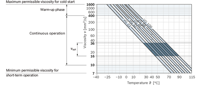
| Cold start | νmax ≤ 1600 mm²/s | NBR2) | ϑSt ≥ -40 °C | t ≤ 3 min, without load (p ≤ 50 bar), n ≤ 1000 rpm, permissible temperature difference between axial piston unit and hydraulic fluid max. 25 K |
| FKM | ϑSt ≥ -25 °C | |||
| Warm-up phase | ν = 400 … 1600 mm²/s | t ≤ 15 min, p ≤ 0.7 • pnom and n ≤ 0.5 • nnom | ||
| Continuous operation | ν = 10 … 400 mm²/s3) | NBR2) | ϑ ≤ +78 °C | measured at port T |
| FKM | ϑ ≤ +103 °C | |||
| νopt = 16 … 36 mm²/s | range of optimum operating viscosity and efficiency | |||
| Short-term operation | νmin = 7 … 10 mm²/s | NBR2) | ϑ ≤ +78 °C | t ≤ 3 min, p ≤ 0.3 • pnom
measured at port T |
| FKM | ϑ ≤ +103 °C |
Selection diagram
Filtration of the hydraulic fluid
Finer filtration improves the cleanliness level of the hydraulic fluid, which increases the service life of the axial piston unit.
A cleanliness level of at least 20/18/15 is to be maintained according to ISO 4406.
At a hydraulic fluid viscosity of less than 10 mm²/s (e.g. due to high temperatures in short-term operation) at the drain port, a cleanliness level of at least 19/17/14 according to ISO 4406 is required.
For example, the viscosity is 10 mm²/s at:
- HLP 32 a temperature of 73°C
- HLP 46 a temperature of 85°C
Operating pressure range
| Pressure at working port A or B (high-pressure side) | Definition | ||
| Nominal pressure | pnom | see table of values | The nominal pressure corresponds to the maximum design pressure. |
| Maximum pressure | pmax | see table of values | The maximum pressure corresponds to the maximum operating pressure within the single operating period. The sum of the single operating periods must not exceed the total operating period. |
| Single operating period | 10 s | ||
| Total operating period | 300 h | ||
| Minimum pressure | pHP min | 25 bar | Minimum pressure on high-pressure side (port A or B) required to prevent damage to the axial piston unit. |
| Rate of pressure change | RA max | 16000 bar/s | Maximum permissible rate of pressure build-up and reduction during a pressure change over the entire pressure range. |
| Pressure at suction port S (inlet) | Definition | ||
| Minimum pressure | ps min | 0.8 bar absolute | Minimum pressure at inlet (suction port S) that is required to avoid damage to the axial piston unit. The minimum required pressure is dependent on the speed of the axial piston unit. (see diagram “Maximum speed”) |
| Maximum pressure | ps max | 30 bar absolute | |
| Case pressure at port T | Definition | ||
| Continuous differential pressure | ΔpT cont | 2 bar | Maximum averaged differential pressure at the shaft seal (case to ambient pressure) |
| Maximum differential pressure | ΔpT max | see diagram “Maximum differential pressure at the shaft seal” | Intermittent differential pressure at the shaft seal (permitted at reduced speed) |
| Pressure peaks | pT peak | 10 bar | t < 0.1 s |
Dimensions
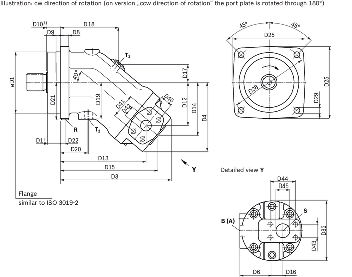
| Size | D1 | D3 | D4 | D6 | D8 | D9 | D10 | D11 | D12 | D13 | D14 | D15 | D16 | D17 | D18 | D19 | D20 | D21 | D22 | D25 | D28 | D29 | D32 | D40 | D41 | D42 | D43 | D44 | |
| mm | mm | mm | mm | mm | mm | mm | mm | mm | mm | mm | mm | mm | mm | mm | mm | mm | mm | mm | mm | mm | mm | mm | mm | mm | mm | mm | mm | mm | |
| 23 | 100 | 0 – 0.022 |
190 | 117 | 60 | 18 | 8 | 25 | 23.2 | 70 | 144 | 88 | 166 | 14 | 25 | 106 | 56 | 42 | 61 | 9 | 118 | 125 | 11 | 106 | 18.2 | 40.5 | 13 | 22.2 | 47.6 |
| 28 | 100 | 0 – 0.022 |
190 | 117 | 60 | 18 | 8 | 25 | 23.2 | 70 | 144 | 88 | 166 | 14 | 25 | 106 | 56 | 42 | 61 | 9 | 118 | 125 | 11 | 106 | 18.2 | 40.5 | 13 | 22.2 | 47.6 |
| 32 | 100 | 0 – 0.022 |
190 | 117 | 60 | 18 | 8 | 25 | 23.2 | 70 | 144 | 88 | 166 | 14 | 25 | 106 | 56 | 42 | 61 | 9 | 118 | 125 | 11 | 106 | 18.2 | 40.5 | 13 | 22.2 | 47.6 |
| 45 | 125 | 0 – 0.025 |
207 | 133 | 64 | 20 | 12 | 32 | 30 | 80 | 155 | 100 | 179 | 20 | 28 | 108 | 63 | 42 | 78 | 11 | 150 | 160 | 13.5 | 118 | 23.8 | 50.8 | 19 | 26.2 | 52.4 |
| 56 | 125 | 0 – 0.025 |
225 | 142 | 68 | 20 | 10 | 32 | 30 | 87 | 171 | 107 | 195 | 23 | 31 | 117 | 70 | 50 | 78 | 11 | 150 | 160 | 13.5 | 128 | 23.8 | 50.8 | 19 | 26.2 | 52.4 |
| 63 | 125 | 0 – 0.025 |
225 | 142 | 68 | 20 | 10 | 32 | 30 | 87 | 171 | 107 | 195 | 23 | 31 | 117 | 70 | 50 | 78 | 11 | 150 | 160 | 13.5 | 128 | 23.8 | 50.8 | 19 | 26.2 | 52.4 |
| 80 | 140 | 0 – 0.025 |
257 | 162 | 73 | 20 | 10 | 32 | 29 | 99 | 196 | 122 | 224 | 25 | 41 | 132 | 83 | 63 | 86 | 11 | 165 | 180 | 13.5 | 138 | 27.8 | 57.2 | 25 | 30.2 | 58.7 |
| 90 | 140 | 0 – 0.025 |
257 | 162 | 73 | 20 | 10 | 32 | 29 | 99 | 196 | 136 | 224 | 25 | 41 | 132 | 83 | 63 | 86 | 11 | 165 | 180 | 13.5 | 138 | 27.8 | 57.2 | 25 | 30.2 | 58.7 |
| 107 | 160 | 0 – 0.025 |
275 | 174 | 89 | 23 | 10 | 40 | 85 | 110 | 213 | 136 | 245 | 20 | 40 | 140 | 85 | 65 | 98 | 12 | 190 | 200 | 17.5 | 150 | 27.8 | 57.2 | 25 | 35.7 | 69.9 |
| 125 | 160 | 0 – 0.025 |
275 | 174 | 89 | 23 | 10 | 40 | 36.5 | 110 | 213 | 136 | 245 | 20 | 40 | 140 | 85 | 65 | 98 | 12 | 190 | 200 | 17.5 | 150 | 31.8 | 66.7 | 32 | 35.7 | 69.9 |
| 160 | 180 | 0 – 0.025 |
294 | 188 | 101 | 25 | 10 | 40 | 37.2 | 121 | 237 | 149 | 271 | 15 | 47 | 158 | 96 | 72 | 108 | 13 | 210 | 224 | 17.5 | 180 | 31.8 | 66.7 | 32 | 35.7 | 69.9 |
| 180 | 180 | 0 – 0.025 |
294 | 188 | 101 | 25 | 10 | 40 | 37.2 | 121 | 237 | 149 | 271 | 15 | 47 | 158 | 96 | 72 | 108 | 13 | 210 | 224 | 17.5 | 180 | 31.8 | 66.7 | 32 | 35.7 | 69.9 |
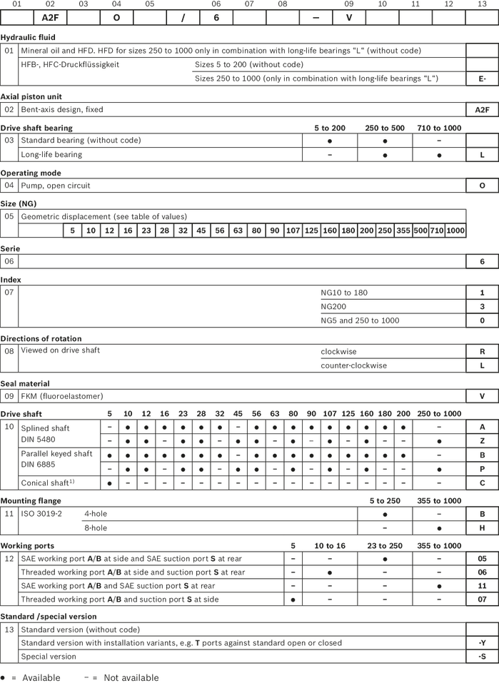
Type code
Rexroth A2FO32/61L-PZB06 Hydraulic Pump Service Manual
Rexroth A2FO32/61L-PZB06 Hydraulic Pump Service Manual Click to download for free
Rexroth A2FO32/61L-PZB06 Hydraulic Pump Service Manual
Related products
-
A2FO Series Axial piston fixed pump
Rexroth A2FO125/61L-VAB05 Axial Piston Hydraulic Pump
Read moreRated 0 out of 5 -
A2FO Series Axial piston fixed pump
Rexroth A2FO12/61R-PZP06 Hydraulic Pump
Read moreRated 0 out of 5

